
Calculator

Products
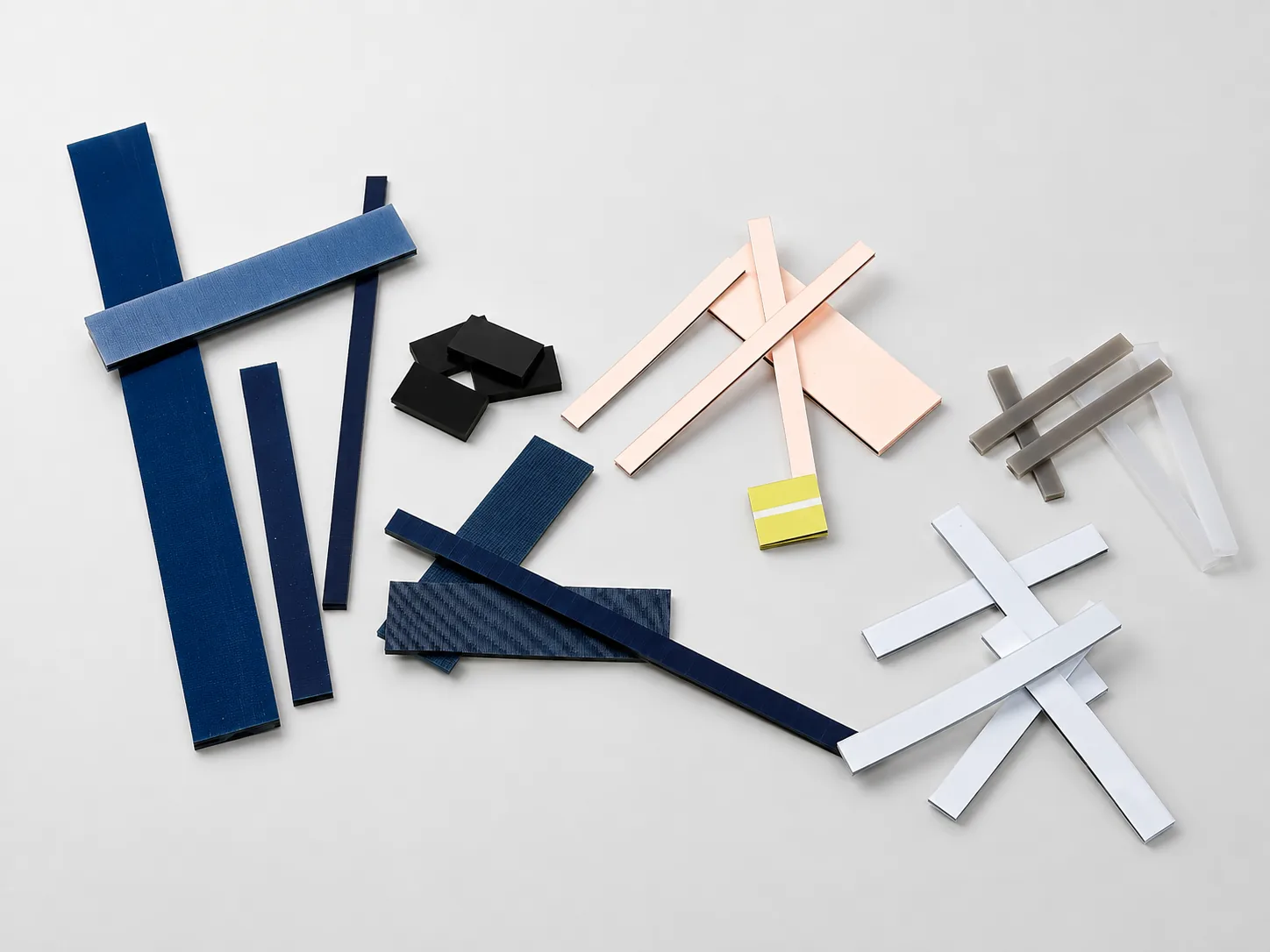
Top-Bound is a Taiwan Zebra Connector manufacturer. Explore elastomeric connectors for LCD and PCB interconnects, compare types and dimensions, and contact us for custom sizing.
Our Zebra Connector products are elastomeric connectors (conductive silicone connectors) that provide reliable electrical connections between LCDs and PCBs. Typical applications include display modules, instruments, medical devices, automotive electronics, and other equipment. Multiple types and custom dimensions are available for inquiry.
Calculator
Digital Multimeter

Electronic Scale

Payment Terminal
Automotive Electronics

Pulse Oximeter

Blood Pressure Monitor
Digital Calipers

Digital Clocks

Digital Watches
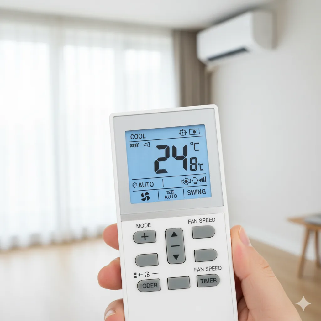
Remote Controls
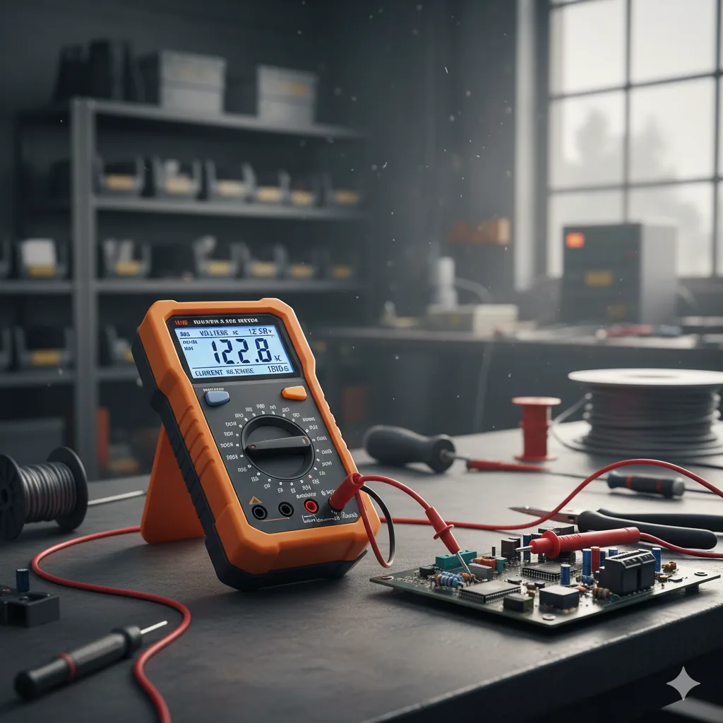
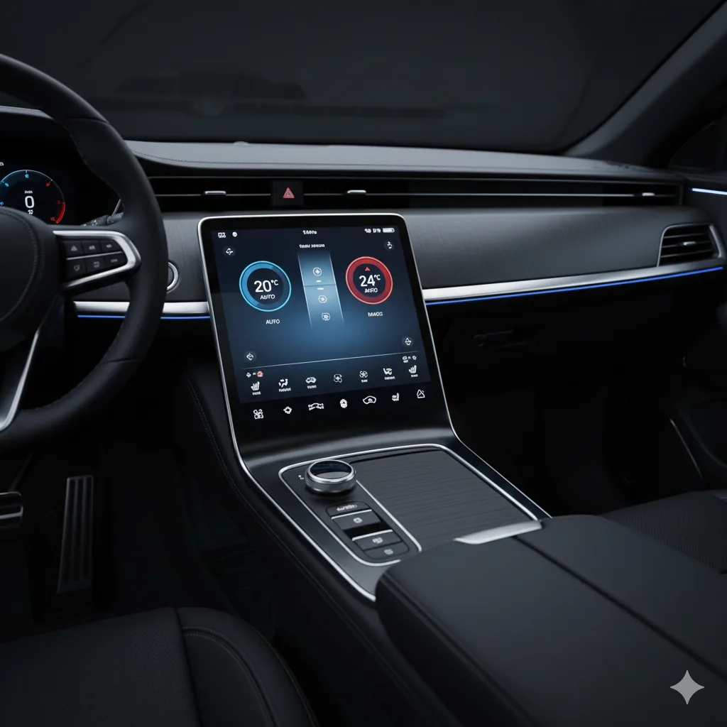
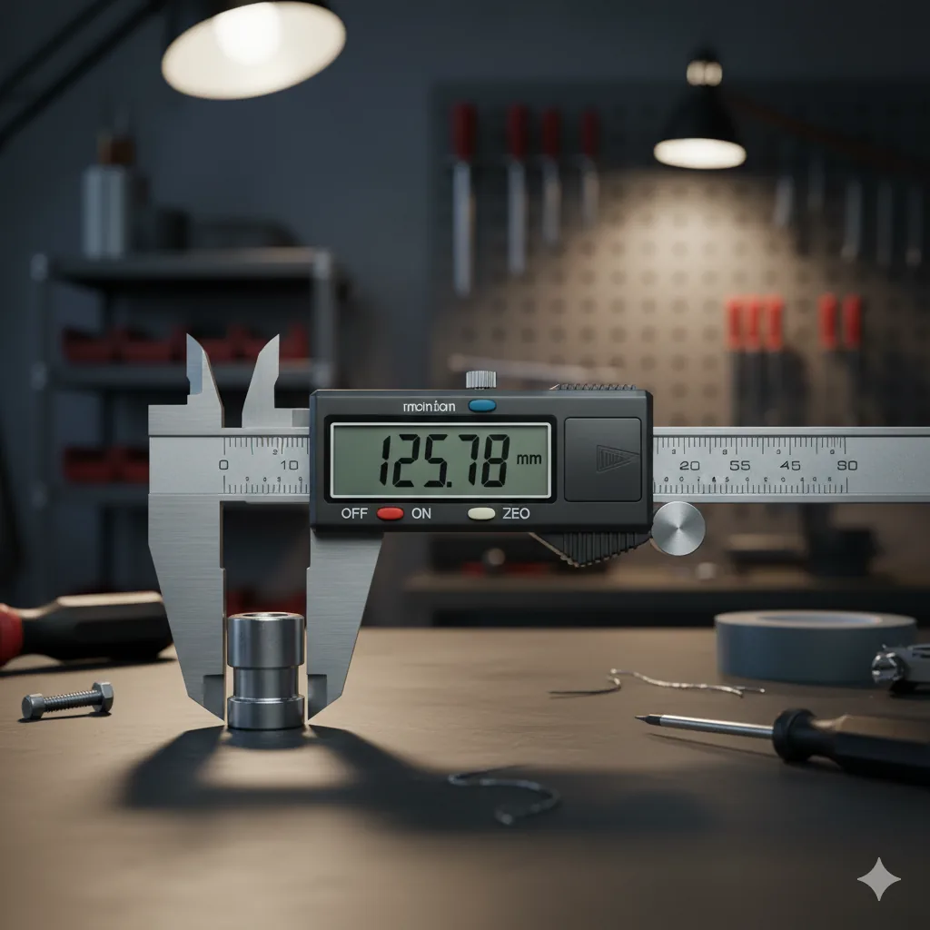
Images are shown for application reference only.
T Type is constructed from alternating layers of conductive and insulating silicone rubber.
T and T2 Type connectors use one or more conductive layers to contact the electrode surfaces of a PCB or LCD.
※ T2 Type has a white insulating coating on both sides.
Dimension symbols follow the original technical drawings.
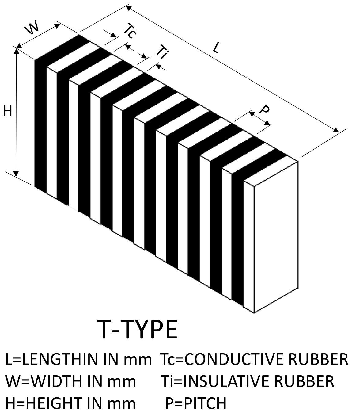
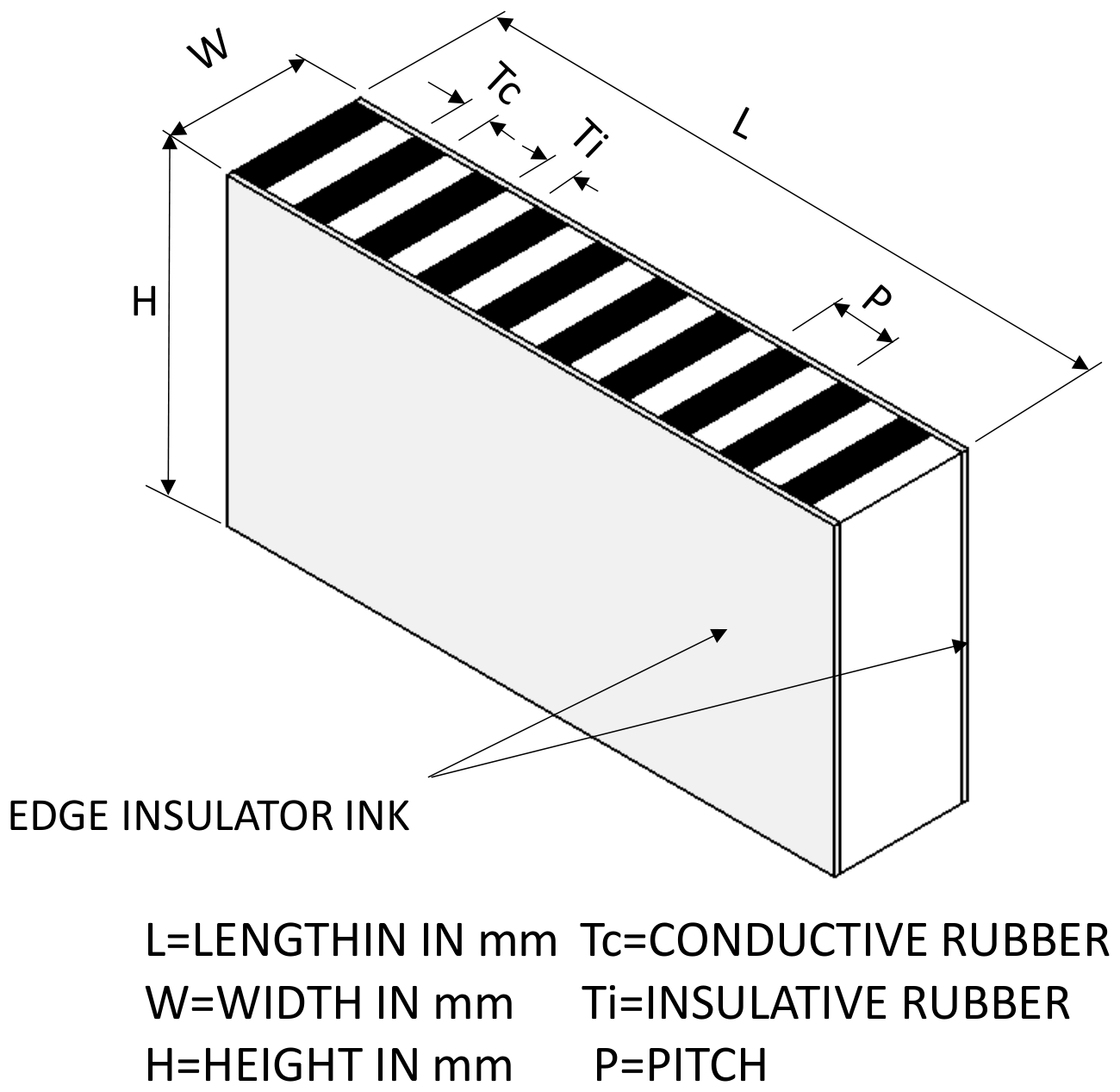
| Item | Symbol | Unit | 0.10 P | 0.18 P | 0.25 P |
|---|---|---|---|---|---|
| Pitch | P | mm | 0.10±0.03 | 0.18±0.05 | 0.25±0.05 |
| Conductive Layer Width | Tc | mm | 0.05±0.02 | 0.09±0.03 | 0.13±0.03 |
| Insulating Layer Width | Ti | mm | 0.05±0.02 | 0.09±0.03 | 0.12±0.03 |
| Length | L | mm |
|
||
| Height | H | mm |
|
||
| Thickness | W | mm |
|
||
Pitch
Conductive Layer Width
Insulating Layer Width
Length
Height
Thickness
| Item | Insulating Rubber | Conductive Rubber |
|---|---|---|
| Volume Resistivity | 1×10¹⁴ Ω·cm | 3–5 Ω·cm |
| Dielectric Breakdown Voltage | 26 kV/mm | — |
| Specific Gravity | 1.20 | 1.20 |
| Hardness | 65°±5° | 70°±5° |
| Tensile Strength | 80 kg/cm | 60 kg/cm |
| Insulation Resistance(@500 V DC) | 1014 ohms | — |
| Operating Temperature Range | −40°C to +180°C | |
| Storage Temperature Range | −40°C to +180°C | |
| Maximum Current Density(@25°C) | — | 1 mA/mm² |
Volume Resistivity
Dielectric Breakdown Voltage
Specific Gravity
Hardness
Tensile Strength
Insulation Resistance(@500 V DC)
Operating Temperature Range
−40°C to +180°C
Storage Temperature Range
−40°C to +180°C
Maximum Current Density(@25°C)
F = 6.2 × D × W × L (g)
For special material properties, dimensional tolerances, or contact resistance requirements, please specify the requirements to our sales team before ordering.
TS Type uses T Type material as the central support structure, with both sides covered by softer insulating silicone rubber. It is suitable for larger LCD display applications.
Dimension symbols follow the original technical drawings.

| Item | Symbol | Unit | 0.10 P | 0.18 P | 0.25 P | 0.05 P |
|---|---|---|---|---|---|---|
| Pitch | P | mm | 0.10±0.03 | 0.18±0.05 | 0.25±0.05 | 0.05±0.02 |
| Conductive Layer Width | Tc | mm | 0.05±0.02 | 0.09±0.03 | 0.13±0.03 | 0.03±0.01 |
| Insulating Layer Width | Ti | mm | 0.05±0.02 | 0.09±0.03 | 0.12±0.03 | 0.02 |
| Conductive Layer Width | W′ | mm |
|
|||
| Length | L | mm |
|
|||
| Height | H | mm |
|
|||
| Thickness | W | mm |
|
|||
Pitch
Conductive Layer Width
Insulating Layer Width
Conductive Layer Width
Length
Height
Thickness
| Item | Insulating Rubber | Conductive Rubber | Side Insulating Rubber |
|---|---|---|---|
| Volume Resistivity | 1×10¹⁴ Ω·cm | 3–5 Ω·cm | 5×10¹⁴ Ω·cm |
| Dielectric Breakdown Voltage | 26 kV/mm | — | 25 kV/mm |
| Specific Gravity | 1.20 | 1.20 | 1.10 |
| Hardness | 65°±5° | 70°±5° | 25°±5° |
| Tensile Strength | 80 kg/cm | 60 kg/cm | 50 kg/cm |
| Insulation Resistance(@500 V DC) | 1014 ohms | — | 8×10¹¹ ohms |
| Operating Temperature Range | −20°C to +100°C | ||
| Storage Temperature Range | −40°C to +180°C | ||
| Maximum Current Density(@25°C) | 1 mA/mm² | ||
Volume Resistivity
Dielectric Breakdown Voltage
Specific Gravity
Hardness
Tensile Strength
Insulation Resistance(@500 V DC)
Operating Temperature Range
−20°C to +100°C
Storage Temperature Range
−40°C to +180°C
Maximum Current Density(@25°C)
1 mA/mm²
F = 2.1 × D × W × L (g)
For special material properties, dimensional tolerances, or contact resistance requirements, please specify the requirements to our sales team before ordering.
TG Type uses T Type material as the central support structure. Both sides use softer foamed insulating silicone rubber than the standard TS side insulation.
Its smooth surface also facilitates assembly, making it suitable for larger LCD applications.
Dimension symbols follow the original technical drawings.

| Item | Symbol | Unit | 0.10 P | 0.18 P | 0.25 P | 0.05 P |
|---|---|---|---|---|---|---|
| Pitch | P | mm | 0.10±0.03 | 0.18±0.05 | 0.25±0.05 | 0.05±0.02 |
| Conductive Layer Width | Tc | mm | 0.05±0.02 | 0.09±0.03 | 0.13±0.03 | 0.03±0.01 |
| Insulating Layer Width | Ti | mm | 0.05±0.02 | 0.09±0.03 | 0.12±0.03 | 0.02 |
| Conductive Layer Width | W′ | mm |
|
|||
| Length | L | mm |
|
|||
| Height | H | mm |
|
|||
| Thickness | W | mm |
|
|||
Pitch
Conductive Layer Width
Insulating Layer Width
Conductive Layer Width
Length
Height
Thickness
| Item | Insulating Rubber | Conductive Rubber | Side Insulating Rubber |
|---|---|---|---|
| Volume Resistivity | 1×10¹⁴ Ω·cm | 3–5 Ω·cm | 5×10¹⁴ Ω·cm |
| Dielectric Breakdown Voltage | 26 kV/mm | — | 25 kV/mm |
| Specific Gravity | 1.20 | 1.20 | 1.10 |
| Hardness | 65°±5° | 70°±5° | 18°±5° |
| Tensile Strength | 80 kg/cm | 60 kg/cm | 50 kg/cm |
| Insulation Resistance(@500 V DC) | 1014 ohms | — | 8×10¹¹ ohms |
| Operating Temperature Range | −20°C to +100°C | ||
| Storage Temperature Range | −40°C to +180°C | ||
| Maximum Current Density(@25°C) | 1 mA/mm² | ||
Volume Resistivity
Dielectric Breakdown Voltage
Specific Gravity
Hardness
Tensile Strength
Insulation Resistance(@500 V DC)
Operating Temperature Range
−20°C to +100°C
Storage Temperature Range
−40°C to +180°C
Maximum Current Density(@25°C)
1 mA/mm²
F = 1.4 × D × W × L (g)
For special material properties, dimensional tolerances, or contact resistance requirements, please specify the requirements to our sales team before ordering.
IR(TG)(TS) uses insulating silicone rubber and is primarily designed for cushioning and protection applications.
Materials, hardness, adhesive backing, and Mylar options can be customized to meet customer requirements.
Dimension symbols follow the original technical drawings.
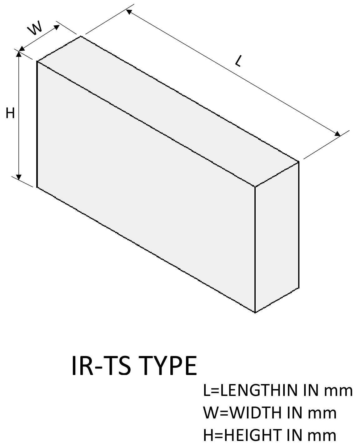
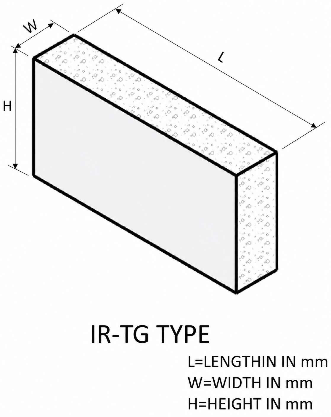
| Item | Symbol | Unit | Range / Tolerance |
|---|---|---|---|
| Length | L | mm |
|
| Height | H | mm |
Data per original specification table |
| Thickness (incl. tape) | W | mm |
|
Length
Height
Data per original specification table
Thickness (incl. tape)
| Item | IR-TS | IR-TG | IR-TSR | IR-TGR |
|---|---|---|---|---|
| Color | Translucent or specified color |
Pink | Transparent or black | Pink |
| Hardness | 20°–70° | 15°±5° | 20°–70° | 15°±5° |
| Silicone rubber | Solid insulating silicone rubber | Foamed silicone sponge | Silicone rubber | Foamed silicone sponge |
| Specific Gravity | 1.08 / 1.15 / 1.2 | 0.6 | 1.08–1.2 | 0.6 |
| Tensile Strength(kg/cm²) | 50 / 74 / 80 | 50 | 50–80 | 50 |
| Elongation(%) | 500 / 400 / 300 | 300 | 230–520 | 300 |
| Volume Resistivity(Ω·cm) | 8×10¹¹ / 1×10¹⁴ / 1×10¹⁴ | 1×10¹¹ | 1×10¹³ | 1×10¹¹ |
| Compression Set(%) | 5–15 | 10–20 | 5–15 | 10–20 |
| Operating Temperature Range | −20°C to +90°C | |||
| Dielectric Breakdown Voltage(kV/mm) | 23–27 | 20–25 | 23–27 | 20–25 |
Color
Hardness
Silicone rubber
Specific Gravity
Tensile Strength(kg/cm²)
Elongation(%)
Volume Resistivity(Ω·cm)
Compression Set(%)
Operating Temperature Range
−20°C to +90°C
Dielectric Breakdown Voltage(kV/mm)
For special material properties, dimensional tolerances, or contact resistance requirements, please specify the requirements to our sales team before ordering.
Use the following reference when selecting connector length, height, width, pitch, and contact spacing. Final specifications should be confirmed based on the product structure and operating conditions.